Lab 4: Digital Audio
Sebastian Heredia | dheredia@g.hmc.edu | October 1, 2025
Introduction
In this lab, the internal peripheral timers of the STM32L432KC MCU were used to drive a small speaker to play music. To implement this function, the PWM timers on the MCU generated square waves to toggle a GPIO pin at a specific frequency and manage note duration. The MCU was programmed to play Für Elise by Beethoven and Blue (Da Be Dee) by Eiffel 65.
Methods & Design
Lab Overview
The goals of the lab were twofold: 1) Build a circuit to enable an I/O pin from the MCU to drive a speaker and 2) Write libraries in C from scratch. To meet the outlined goals, two timers were developed. First, timer TIM15 was used to generate precise millisecond delays for note durations. Second, timer TIM16 was used to produce PWM signals corresponding to musical notes. The GPIO pin PA6 was configured to use alternate function 14 so that the TIM16 output could be routed to the audio circuit. Then, the main program iterated through arrays containing note frequencies (Hz) and durations (ms), updating the PWM output for each note and delaying the program execution according to the specified note length. This setup allowed the MCU to function as a digital audio synthesizer capable of playing sequences of notes with varying pitches.
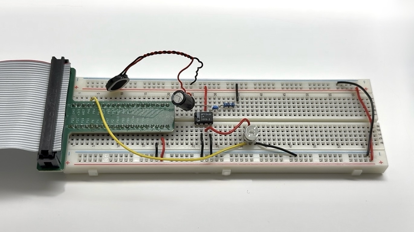 Figure 1: Physical circuit setup for MCU, potentiometer, and speaker components.
Custom headers were written for the RCC, GPIO, and TIM modules to allow direct access to registers and bit manipulation. This was necessary to configure clocks, timers, and GPIOs. By defining the timer registers in TIM.h as structured data, specific registers could be modified for PWM output or delay control.
Clock Control
The system clock, running at 80MHz, was routed through the reset-control clock (RCC) to the timers and GPIO peripherals. The timer TIM16 input clock was scaled down using a prescaler (PSC) of 79 to generate frequency of 1 MHz. The timer TIM15 clock prescaler was set to 3000 to correctly span the full range of delays. Enabling the peripherals and setting prescalers involved setting the appropriate bits in the RCC registers, specifically in AHB2ENR and APB2ENR. The prescaler values were chosen to accommodate the range of frequencies required for musical notes and the range of durations found in the note arrays.
Timer Setup
TIM15 was configured to generate precise delays corresponding to note durations. Its prescaler scaled the 80MHz system clock down to a practical frequency for millisecond timing. The auto-reload register (ARR) was set based on the desired delay in milliseconds by scaling the system clock, and the program waited for the update interrupt flag before continuing execution. This method allowed accurate timing for each note and enabled simple modificaiton of tempos by modifying the note duration arrays.
TIM16 was configured to generate PWM signals for audio output. The prescaler reduced the clock to 1MHz, and the ARR was calculated as the timer clock divided by the note frequency. The capture/compare register CCR1 was set to half of the auto-reload value to produce a square wave with a 50% duty cycle. PWM mode 1 with preload enabled ensured smooth waveform output. The output was routed to PA6 using alternate function 14. Frequency changes were handled dynamically using the setPWM() function, which updated ARR and CCR1 for each note without glitches.
The main program first configured wait states and system clocks, then enabled the necessary GPIO and timer peripherals. TIM16 PWM was initialized with 40 Hz (A4) and the program played Für Elise by iterating through the note arrays, updating TIM16 frequency, and delaying each note with TIM15. After a one-second pause, TIM16 was reinitialized and the program played Blue (Da Ba Dee). Finally, TIM16 was stopped to end the tunes.
Calculations
The prescaler (PSC) value divides the system clock frequency of 80MHz by any factor between 1 and 65,536. Figure 2a anf Figure 2b below show calculations for the maximum and minimum values for frequency and duration components based on the selected PSC and contraints for the auto-reload register (ARR) noted in the STM32L432KC Reference Manual.
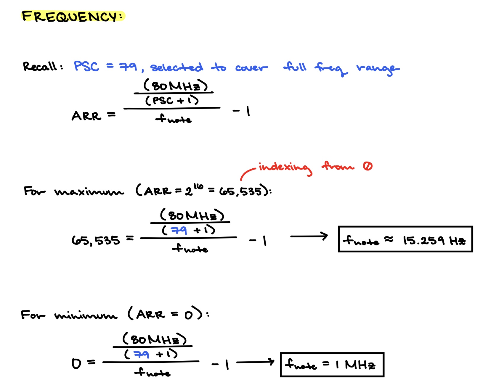
Figure 2a: Frequency range based on PSC = 79.
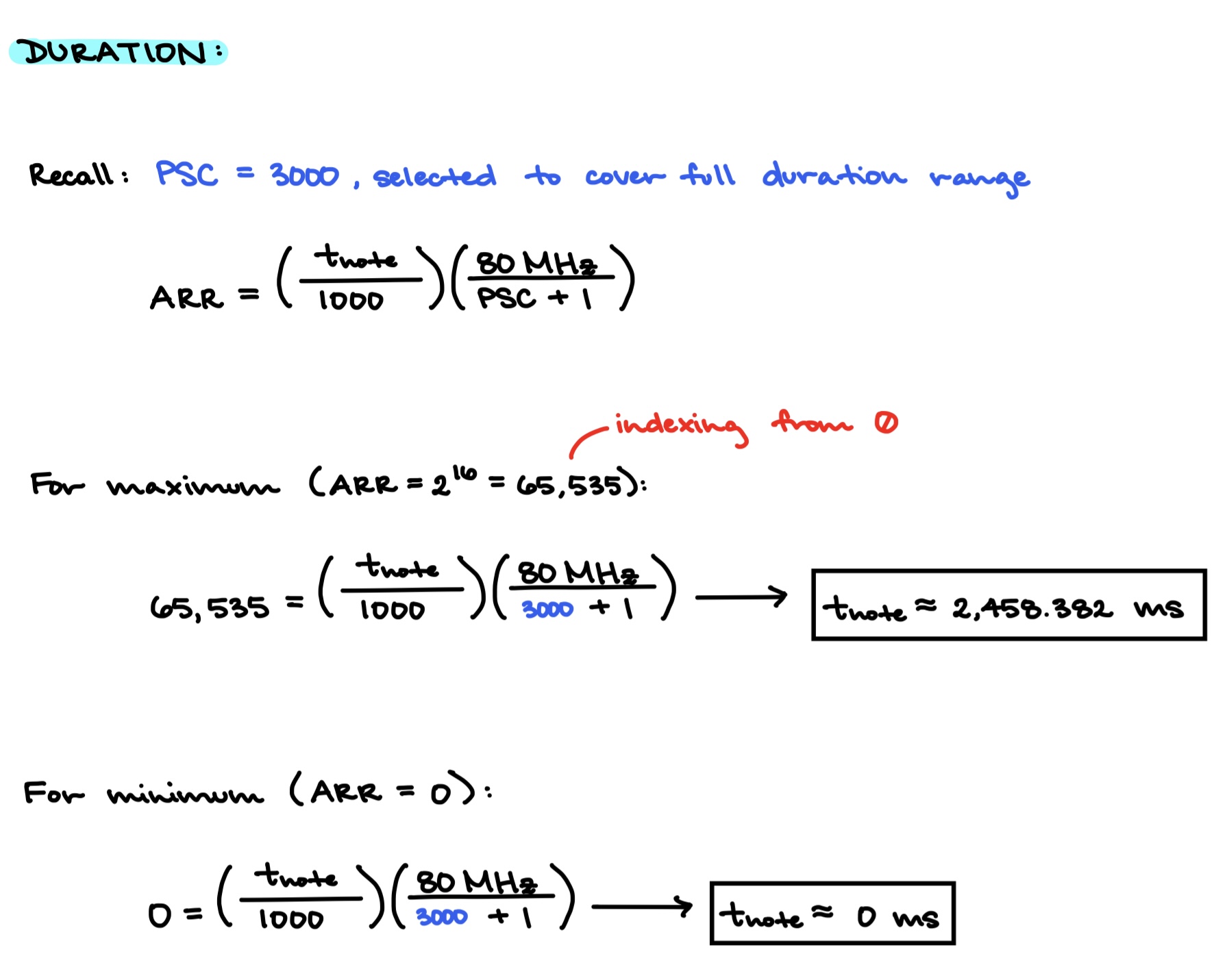
Figure 2b: Duration range based on PSC = 3000.
After verifying the maximum and minimum frequencies and durations according to the selected PSC values, the frequency accuracy was quntified for the range 200Hz to 1,000Hz. All frequencies in this range were to be within 1% of their expected value. The calculations shown in Figure 3 below verify this accuracy.
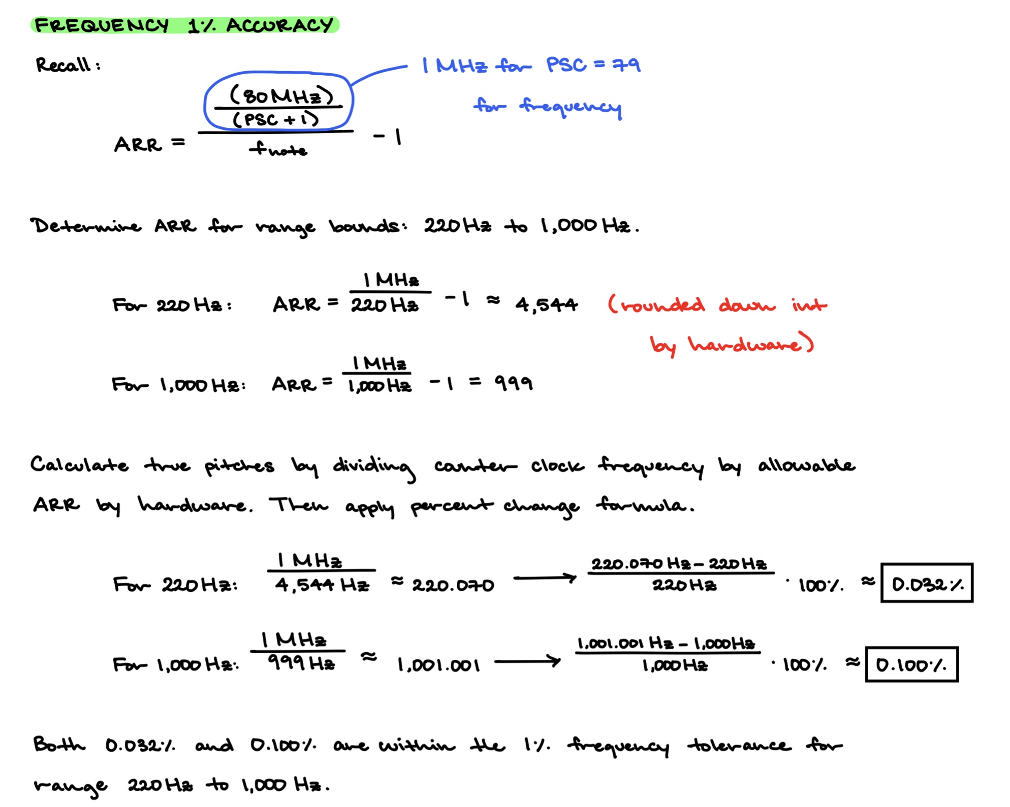
Figure 3: Calculations verify that pitches were within 1% across range 220Hz to 1,000Hz.
Technical Documentation
The TIM16 output on PA6 was connected to a small speaker through an LM348 audio amplifier to boost the 5.0V MCU signal to audible levels. A 10kΩ potentiometer allowed volume control. This setup provided sufficient volume while protecting the MCU from excessive current draw. Figure 4 below shows the electrical schematic for the design. The code for this project can be accessed through GitHub.
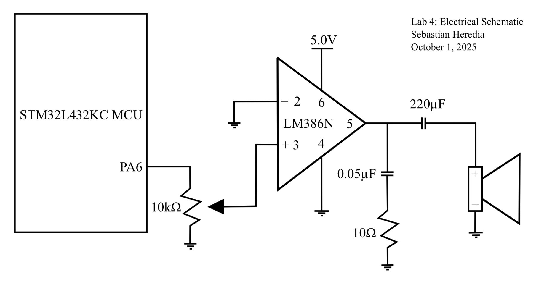 Figure 4: Schematic showing the design used a LM386N amplifier to provide sufficient voltage through the speaker.
Results & Discussion
The final implementation successfully played Für Elise and Blue (Da Be Dee) with correct pitches and note durations. The millisecond delay provided by TIM15 and the PWM output from TIM16 worked together to generate accurate and clear musical notes. Volume control through the potentiometer functioned as intended.
Conclusion & Demo
All designs were successfully implemented. The lab took 18 hours to complete.
The lab reinforced the importance of precise timers configuration and sequencingin PWM updates for digital audio. Notable challenges included ensuring smooth PWM output when changing frequencies, accurately calculating PSC and ARR values for a wide range of notes, and finding base addresses in the MCU datasheet. After overcoming these challenges, the implementation was capable of playign mutiple songs with correct pitch and timing, which provided practical experience with bare-metal C programming.
AI Prototype
The purpose of the AI Prototype is to experiment with usign AI as a coding assistant to navigate memory maps and guide the configuration of various peripherals. The following prompt was entered to ChatGPT 5.0.
- What timers should I use on the STM32L432KC to generate frequencies ranging from 220Hz to 1kHz?
- What’s the best choice of timer if I want to easily connect it to a GPIO pin?
- What formulae are relevant, and what registers need to be set to configure them properly?
For Question 1, the LLM suggested using TIM1, TIM2, TIM15, TIM16, TIM17 as they are general-purpose or advanced timers capable of direclty driving GPIO. This is very resonable to me because I implemented TIM15 and TIM16 in my own design approach. Notably, the STM32L432KC Reference Manual. was provided along with the prompts above.
For Question 2, the LLM proposed using TIM2 as a timer since TIM2_CH1 is available on PA0 which is a very accessible GPIO pin. The LLM also recommended usign TIM16_CH1 on PA6. This is reasonable to me because I used PA6 to map directly to GPIO pins with alternate function mode.
For Question 3, the LLM provided the formulas shown in Figure 5 below as well as advice on how to configure registers correctly. Both the formulas and register configuration approach are valid.
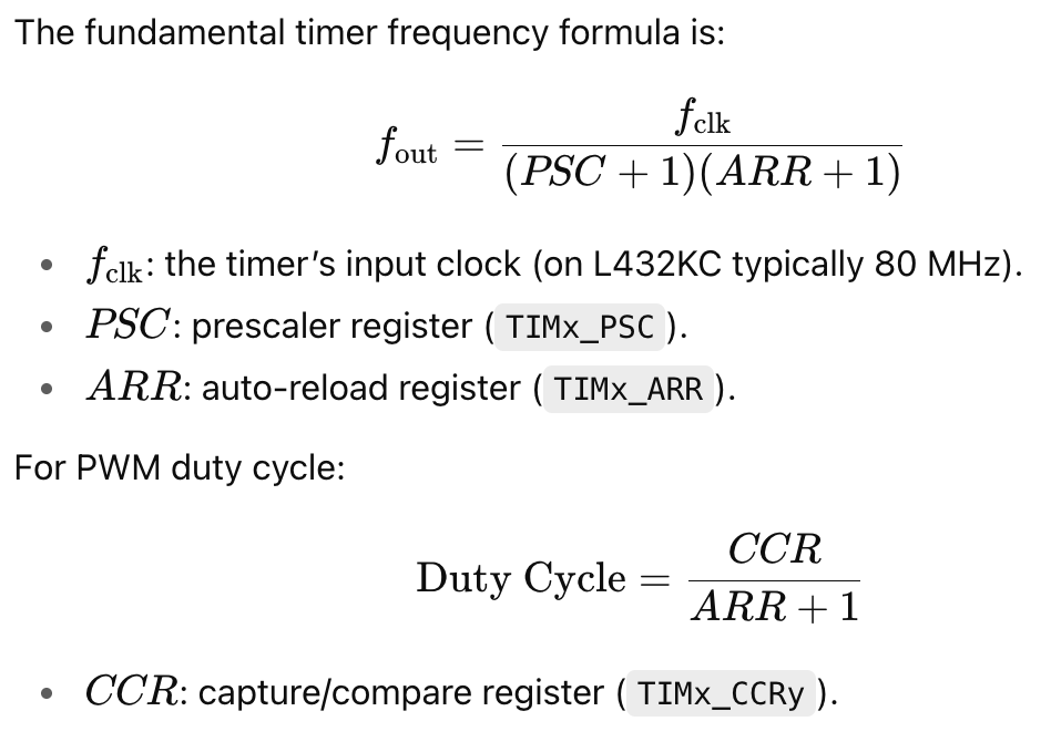
Figure 5: LLM response to relevant formula for selecting ARR and PSC.